
The arc flash boundary is the distance from an exposed, energized conductor at which incident energy reaches 1.2 cal/cm² (5.02 J/cm²), the threshold for a second-degree burn. Cross that line without arc-rated PPE and a compliant energized-work control plan, and you are unprotected against a thermal event that can cause permanent injury in fractions of a second.
Three immediate rules govern every energized work situation:
- Stay outside the arc flash boundary unless you are a qualified person with appropriate arc-rated PPE and a completed energized electrical work permit.
- Arc flash and shock approach boundaries are independent. The arc flash boundary can fall inside or outside the limited and restricted approach boundaries. Calculate each separately and apply the more restrictive requirement when they overlap.
- LOTO is always the first choice. When de-energizing is feasible, do it. Energized work inside the boundary is justified only when de-energizing creates greater hazards or is infeasible by design.
Arcflashtraining provides NFPA 70E-compliant training and certification that covers arc flash boundary determination, PPE selection, and energized-work permit procedures for industrial and commercial teams across the United States.
Table of Contents
- What does the arc flash boundary actually mean physically?
- How do the three approach boundaries differ from each other?
- How do you determine the arc flash boundary distance?
- What do typical arc flash boundary distances look like in practice?
- What must you do when working inside the arc flash boundary?
- Program-level implementation: what safety managers get wrong
- Key Takeaways
- What the field actually teaches you about arc flash boundaries
- Arcflashtraining: from boundary calculations to compliant teams
- Useful sources and standards for your arc flash program
What does the arc flash boundary actually mean physically?
The number 1.2 cal/cm² is not arbitrary. It represents the incident energy level at which bare skin sustains a second-degree burn, the point where tissue damage becomes serious and potentially permanent. NFPA 70E and OSHA guidance both anchor the arc flash boundary definition to this threshold, which means the boundary is not a fixed line on a floor plan. It is a calculated outcome that changes with every variable in the electrical system.
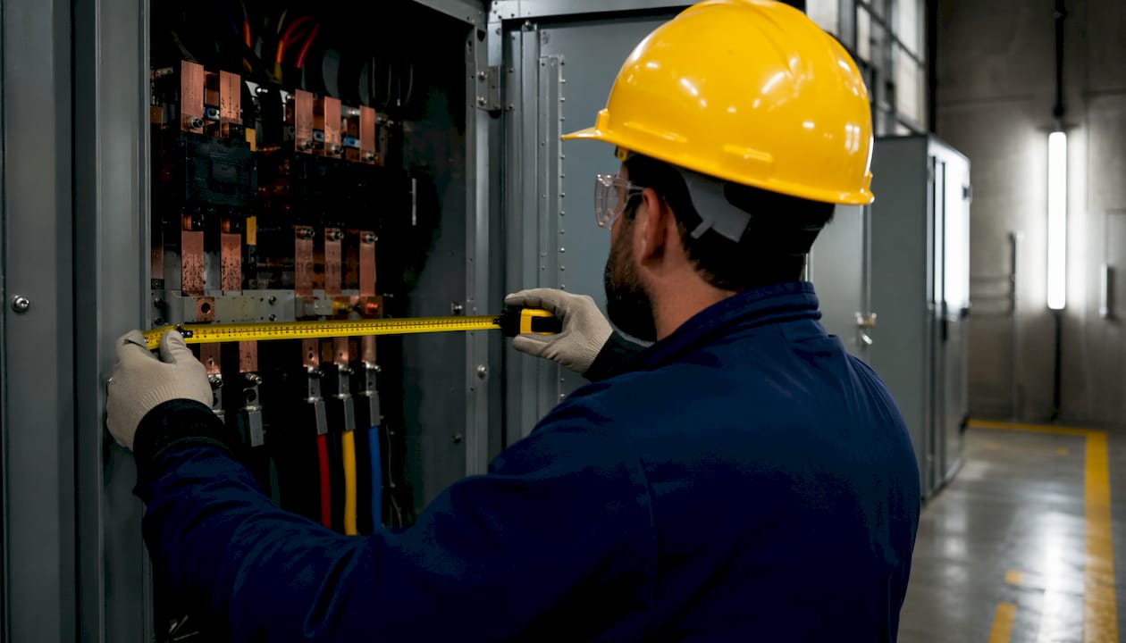
Incident energy is measured in calories per square centimeter (cal/cm²) and describes how much thermal energy an arc flash event would deliver to a worker's body at a given distance. Think of it as the heat dose at a specific point in space during an arc event. The boundary is simply the radius at which that dose equals 1.2 cal/cm².
What this means practically for safety programs:
- PPE selection is driven by the calculated incident energy at the working distance, not by the boundary threshold itself. A worker at 18 inches from a 480 V panel might face 8 cal/cm² of incident energy, requiring an arc-rated suit rated well above the 1.2 cal/cm² boundary value.
- Access control and labeling depend on where the boundary falls relative to normal work positions and traffic paths.
- Energized-work permits are triggered the moment a qualified person must work inside the boundary.
- Equipment labels must communicate the boundary distance and minimum PPE requirements so workers can make real-time decisions before they approach.
The boundary definition also informs how safety managers write procedures. A panel with a 4-foot arc flash boundary requires different access controls than one with a 15-foot boundary, even if both operate at the same nominal voltage.
How do the three approach boundaries differ from each other?
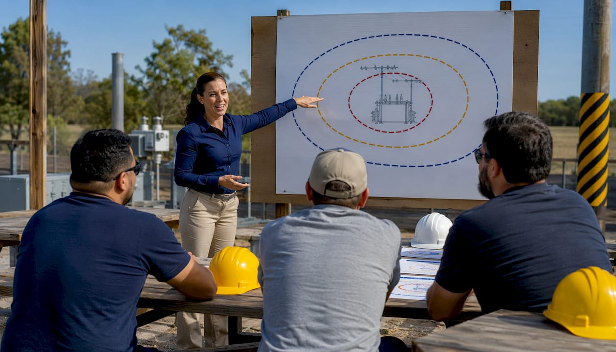
OSHA identifies three approach boundaries around energized electrical equipment, each protecting against a different hazard. Treating them as a single layered system is a common and dangerous oversimplification.
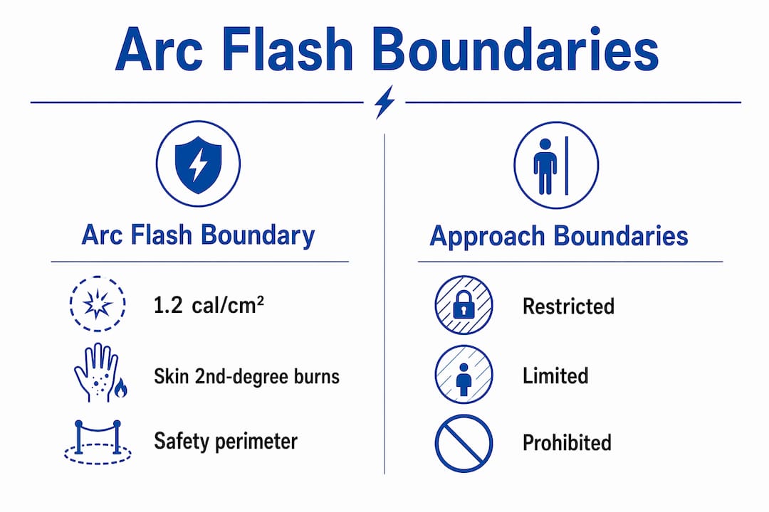
| Boundary | Hazard Protected Against | Who May Enter | Key Controls Required |
|---|---|---|---|
| Arc Flash Boundary | Thermal (arc flash burns) | Qualified persons only; unqualified only under close supervision with appropriate PPE | Arc-rated PPE matched to incident energy; energized work permit |
| Limited Approach Boundary | Electric shock | Unqualified persons may enter only under continuous supervision by a qualified person | Qualified person escort; shock PPE |
| Restricted Approach Boundary | Electric shock (highest risk) | Qualified persons only | Insulated tools; shock PPE; no uninsulated conductive objects |
A few points that catch teams off guard:
- The restricted approach boundary is always inside the limited approach boundary. That relationship is fixed.
- The arc flash boundary has no fixed geometric relationship to either shock boundary. It can be smaller than the restricted approach boundary on low-fault, fast-clearing systems, or it can extend 10 feet beyond the limited approach boundary on high-fault industrial buses.
- When the arc flash boundary extends beyond the limited approach boundary, arc flash rules govern access for anyone in that outer zone, even though they have not crossed the shock boundary yet.
Pro Tip: When writing site procedures, map all three boundaries for each piece of equipment and mark the outermost boundary as the first controlled access point. Do not assume the shock boundaries define the perimeter.
The priority rule is straightforward: apply whichever boundary is more restrictive for the hazard present. A worker standing between the arc flash boundary and the limited approach boundary faces thermal risk even if shock risk is lower at that distance. Arc flash controls apply.
How do you determine the arc flash boundary distance?
Two accepted methods exist under U.S. standards, and choosing between them depends on the complexity of the system and the precision required.
NFPA 70E table method vs. IEEE 1584 calculation
NFPA 70E table method assigns PPE categories based on task type and equipment parameters. It is faster and does not require detailed fault-current data, but it applies only to equipment within defined voltage and fault-current ranges. When equipment falls outside those parameters, the table method cannot be used.
IEEE 1584 is the detailed incident-energy calculation standard. It uses measured or modeled system data to compute incident energy at a specific working distance, from which the arc flash boundary is derived. IEEE 1584 is more precise and applies to a wider range of equipment configurations.
Step-by-step process for an incident-energy calculation
- Collect system data. Gather available fault current (bolted fault current in kA), system voltage, conductor configuration (open air vs. enclosed), enclosure dimensions, and upstream protective device characteristics (type, rating, clearing time).
- Determine arcing current. Using IEEE 1584 equations, calculate the predicted arcing current for the system. This is typically lower than bolted fault current and varies with enclosure geometry.
- Identify clearing time. Determine how long the upstream protective device takes to clear the arcing fault at the calculated arcing current. This is often read from a time-current curve (TCC).
- Select working distance. Use the task-specific working distance from NFPA 70E tables or site-specific task analysis (commonly 18 inches for low-voltage panels, 24 inches for MCCs).
- Calculate incident energy. Apply the IEEE 1584 equations to compute incident energy (cal/cm²) at the working distance.
- Derive the arc flash boundary. Solve for the distance at which incident energy equals 1.2 cal/cm². That distance is the arc flash boundary.
- Document and label. Record the boundary distance, incident energy at working distance, required PPE arc rating, and equipment identifiers on the arc flash label.
Key input variables and their effect on the boundary
| Variable | Effect on Arc Flash Boundary |
|---|---|
| Available fault current | Higher fault current → more energy → larger boundary |
| Protective device clearing time | Longer clearing time → more energy delivered → larger boundary |
| Working distance | Shorter working distance → higher incident energy at that point |
| Enclosure geometry | Enclosed equipment concentrates energy → larger boundary than open air |
| Conductor configuration | Affects arcing current prediction in IEEE 1584 |
Pro Tip: Prefer IEEE 1584 over the NFPA 70E table method whenever you have reliable system data. The table method can be conservative in ways that lead to over-specified PPE, or it may not apply at all for equipment outside its defined parameters. IEEE 1584 gives you a defensible, site-specific number.
What do typical arc flash boundary distances look like in practice?
Arc flash boundaries can range from less than one foot to over 100 feet depending on available fault current, clearing time, and equipment configuration. Voltage alone tells you almost nothing about where the boundary falls.
| Equipment Scenario | Typical AFB Distance Range |
|---|---|
| Residential-style panel, low fault current, fast breaker | Less than 1 ft |
| 480 V MCC, moderate fault current, standard breaker | 2–6 ft (varies significantly) |
| 480 V switchgear, high fault current, slow clearing | 10 ft |
| 15 kV metal-clad switchgear, utility-level fault current | 20–100+ ft |
A 480 V panel worked example
Consider a 480 V motor control center with 20 kA available fault current and a 100A molded-case circuit breaker with a clearing time of 0.05 seconds at the arcing current level. Using IEEE 1584 with an 18-inch working distance, the calculated incident energy at that distance might be approximately 8 cal/cm². Solving for the distance at which incident energy drops to 1.2 cal/cm² yields an arc flash boundary of roughly 4–5 feet for this configuration.
Change one variable. If the upstream breaker is slow to clear (say, 0.5 seconds due to a coordination issue), the incident energy at 18 inches could exceed 40 cal/cm², and the arc flash boundary could push out to 15 feet or more. Same voltage. Dramatically different boundary.
Why distances vary so widely:
- Fault current magnitude is the single largest driver. A high-fault-current bus releases far more energy per unit time than a low-fault-current circuit.
- Clearing time multiplies the effect of fault current. A breaker that takes ten times longer to clear delivers roughly ten times the energy.
- Enclosure geometry concentrates the arc blast, increasing incident energy compared to open-air configurations.
- Working distance is inversely related to incident energy. Moving the worker back reduces exposure, but the boundary distance itself does not change.
Never assume a fixed boundary distance for a voltage class. Always calculate.
What must you do when working inside the arc flash boundary?
Working inside the arc flash boundary is not prohibited, but it is controlled. NFPA 70E and OSHA both require a structured approach before any qualified person crosses that line on energized equipment.
Step-by-step controls for energized work inside the boundary
- Perform a risk assessment. Identify the specific task, the hazard (arc flash incident energy and shock voltage), and whether de-energizing is feasible. Document the justification for energized work.
- Complete an energized electrical work permit. Audit-ready documentation is required for work inside the restricted approach boundary or where an arc flash hazard exists. The permit must identify the equipment, the task, the hazard level, and the controls in place.
- Apply LOTO where feasible. If any portion of the task can be performed with the equipment de-energized, do it. Reserve energized work for tasks that genuinely require it.
- Select PPE rated to the calculated incident energy. Arc-rated PPE is reported as ATPV or EBT. The arc thermal performance value (ATPV) is the incident energy level at which the garment has a 50% probability of preventing a second-degree burn. The energy breakopen threshold (EBT) is the level at which the garment may break open. Choose PPE whose ATPV or EBT rating meets or exceeds the calculated incident energy at the working distance, not merely the 1.2 cal/cm² boundary threshold.
- Use insulated tools and shock PPE. Inside the restricted approach boundary, insulated tools and voltage-rated gloves are required in addition to arc-rated PPE.
- Establish rescue planning. Identify who will respond if an incident occurs, confirm first-aid resources, and brief the team before work begins.
- Supervise and document. A qualified person must supervise the work. Training records and permit copies must be retained for audit purposes.
Pro Tip: Engineering controls reduce incident energy before PPE is ever needed. Faster-clearing upstream devices, zone-selective interlocking, remote racking equipment, and portable arc flash barriers can all shrink the incident energy at the working distance, sometimes enough to drop a PPE category. Evaluate these options during the arc flash study, not after an incident.
NFPA 70E requires that workers performing energized electrical work be trained and qualified. OSHA's general industry standards (29 CFR 1910 Subpart S) reinforce this, and OSHA inspectors look for documented training as evidence of compliance, not just PPE on the shelf.
Program-level implementation: what safety managers get wrong
Most arc flash incidents that result in citations or injuries share a common thread: the program treated boundaries as a one-time calculation rather than a living part of the safety management system.
When to re-evaluate arc flash boundaries
Boundaries are dynamic and must be re-evaluated whenever system conditions change. Specific triggers include:
- Changes in utility fault current (common after utility infrastructure upgrades)
- Replacement or resetting of upstream protective devices
- Addition or removal of generation sources (including on-site generators and solar)
- Equipment modifications or replacements
- Changes in conductor configuration or enclosure type
Documentation and labeling requirements
Equipment labels should include nominal system voltage, the arc flash boundary distance, and the PPE requirements. Including shock approach boundary distances on the same label is a recommended best practice that reduces the chance of a worker applying the wrong control. Visual demarcation (floor tape, warning signs) is not legally required for arc flash boundaries but is strongly recommended, particularly near the limited approach boundary where unqualified personnel might otherwise wander in.
Audit-ready documentation means:
- Completed energized electrical work permits retained on file
- Training records showing worker qualification and training dates
- Arc flash study reports with calculation inputs, outputs, and equipment identifiers
- Labeling policy that specifies update triggers and label format
Common misconceptions to correct
"The arc flash boundary is always the outermost boundary." Not true. As OSHA clarifies, the arc flash boundary can fall inside the restricted approach boundary on low-fault, fast-clearing systems. Calculate each boundary independently and never assume a hierarchy based on voltage or equipment class.
"Once the arc flash study is done, we're covered." A study is a snapshot of system conditions at a point in time. Without a reassessment policy tied to system changes, the study becomes inaccurate and the labels become misleading.
"PPE rated above 1.2 cal/cm² is sufficient for any work inside the boundary." The 1.2 cal/cm² threshold defines the boundary location, not the PPE requirement. PPE must match the calculated incident energy at the actual working distance, which is almost always higher.
Program owner checklist
- Establish a written policy for arc flash study reassessment, including specific triggers and a maximum reassessment interval.
- Maintain a labeling standard that specifies required label content, format, and update procedures.
- Schedule recurring NFPA 70E training, not a single onboarding session. NFPA 70E recommends training at intervals that reflect changes in standards and site conditions.
- Integrate arc flash boundary data into energized-work permit templates so workers cannot complete a permit without referencing the current boundary and incident energy values.
- Conduct periodic mock audits against OSHA 29 CFR 1910 Subpart S and NFPA 70E to identify gaps before an inspector does.
Pro Tip: Coordinate arc flash studies with electrical testing records and protective device maintenance logs. A breaker that has not been tested or maintained may not clear at its rated time, which means the clearing time used in your study is optimistic and the actual incident energy could be higher than calculated.
Key Takeaways
The arc flash boundary is a calculated, dynamic distance, not a fixed line, and every energized work decision in your facility should be anchored to the 1.2 cal/cm² threshold, independent boundary calculations, and current system data.
| Point | Details |
|---|---|
| 1.2 cal/cm² threshold | The arc flash boundary is the distance where incident energy equals 1.2 cal/cm²; PPE must match the actual incident energy at working distance, which is typically higher. |
| Three independent boundaries | Arc flash, limited approach, and restricted approach boundaries protect against different hazards and must each be calculated separately. |
| Boundaries are dynamic | Re-evaluate after any change to fault current, clearing time, protective devices, or equipment configuration. |
| Documentation is compliance | Energized work permits, training records, and labeled equipment are what auditors and OSHA inspectors look for first. |
| Arcflashtraining for program support | Arcflashtraining delivers NFPA 70E-compliant training, certification, and audit-ready documentation for teams across the United States. |
What the field actually teaches you about arc flash boundaries
There is a gap between how arc flash boundaries are taught in a classroom and how they get applied in a real facility, and it tends to show up in the same three places every time.
The first is distance assumptions. Teams that have done an arc flash study often remember a number, say "four feet," and apply it everywhere. Four feet becomes the informal rule for the whole plant, regardless of what the labels on individual pieces of equipment actually say. That is how workers end up standing inside a 15-foot boundary on a high-fault switchgear lineup wearing PPE rated for a 4-foot scenario.
The second is documentation drift. The study gets done, labels go up, and then a breaker gets replaced or a utility upgrade changes the available fault current. Nobody updates the study. The labels are now wrong, the permits reference outdated incident energy values, and the program looks compliant on paper while the actual hazard has grown.
The third is PPE selection confusion. The 1.2 cal/cm² boundary threshold is not the PPE specification. Workers who understand this conceptually sometimes still reach for a Category 2 suit because "we're just inside the boundary." The suit needs to match the incident energy at the working distance, which on a 480 V MCC with slow clearing could be 12 or 20 cal/cm².
What actually moves the needle in training is specificity. When workers see their own facility's equipment labels, run through a permit for a task they actually perform, and practice donning PPE rated to a real calculated value, compliance sticks. Generic awareness training does not produce the same result. The NFPA 70E safety guides and hands-on drills are where the knowledge converts to habit.
Arcflashtraining: from boundary calculations to compliant teams
Knowing where the arc flash boundary falls is only half the job. The other half is making sure every qualified person on your team understands what that boundary means, what PPE to wear, and how to complete a compliant energized-work permit before they cross it.
Arcflashtraining delivers NFPA 70E electrical safety training and certification for industrial and commercial organizations nationwide, in whatever format fits your operation: onsite at your facility, live virtual instructor-led sessions, multi-site custom programs, or train-the-trainer delivery. Every course is led by CSP-credentialed instructors and includes certification and audit-ready documentation your team can hand to an OSHA inspector or internal auditor. Clients range from Fortune 500 manufacturers and utilities to data centers and healthcare facilities.
If your organization has recently completed an arc flash study, is preparing for energized work, or has identified gaps in your current program, that is the right time to schedule training. Contact Arcflashtraining to request a quote or schedule a session for your team.
Useful sources and standards for your arc flash program
Build your program documentation around primary sources. These are the references that carry weight with OSHA inspectors and technical reviewers.
- OSHA: Protecting Employees from Electric-Arc Flash Hazards — OSHA's primary guidance document on arc flash, including the 1.2 cal/cm² boundary definition and PPE requirements. Copy this into your program binder as the regulatory anchor.
- OSHA: Establishing Boundaries Around Arc Flash Hazards — Covers all three approach boundaries, who may enter each, and the priority rule when arc flash and shock boundaries overlap. Use this when writing site access procedures.
- NFPA 70E: Standard for Electrical Safety in the Workplace — The primary U.S. standard governing energized electrical work, PPE categories, energized-work permits, and training requirements. Available through NFPA directly; your safety program must reference the current edition.
- IEEE 1584: Guide for Performing Arc-Flash Hazard Calculations — The technical standard for incident-energy calculations. Required reading for the engineer performing your arc flash study. The 2018 edition introduced significant updates to the calculation model.
- Virginia Tech EHS: Approach Boundaries — A clear institutional explainer on ATPV, EBT, and PPE selection that is useful for training materials and worker reference.
- Fluke: Understanding the Arc Flash Boundary — Practical overview of boundary distance variability and reassessment triggers; useful for communicating the dynamic nature of boundaries to non-engineering stakeholders.
- Safeopedia: A Primer on Arc Flash Boundaries — Covers labeling requirements and recommended label content; useful when developing or auditing your facility's labeling standard.
For audit purposes, keep the OSHA guidance documents, your current arc flash study report, equipment labels, energized-work permits, and training records in a single accessible location. That package is what a compliance inspection looks for first.